
Get Tech Tips
Subscribe to free tech tips.
Compressor Failure Diagnostic Checklist

Industry data shows that up to 40% of compressors returned under warranty have no fault found. Technicians often blame the compressor when another component is the root cause. This checklist is designed to help you definitively confirm compressor failure, saving time, money, and unnecessary replacements. Let's make sure it's truly bad before we cut it out.
Part 1: Confirming Electrical Failure
This section will guide you through a systematic electrical diagnosis to verify the health of the compressor and its related components.
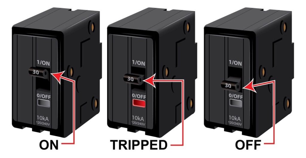
Step 1: Initial Assessment at the Panel
Your first check starts where the power does. This assessment helps you understand the initial state of the system.
Has a breaker tripped, or has a fuse blown?
- YES: This indicates a likely dead short or a component drawing excessively high current. Proceed to Step 2: The Short-to-Ground Test.
- NO: The issue is likely not a direct short to ground. Proceed to Step 3: Verifying Voltage & Components.
Step 2: The Short-to-Ground Test
If the breaker tripped, you must find the short.
1. SHUT OFF ALL POWER at the disconnect and verify that the circuit has no power.
2. Disconnect the compressor wires.
3. Set your multimeter to measure ohms (Ω).
- Pro Tip: Use the manual range setting on your meter, not auto-range. Auto-ranging can give confusing readings by switching to different scales (kΩ, MΩ). Manually select the standard Ohms scale.
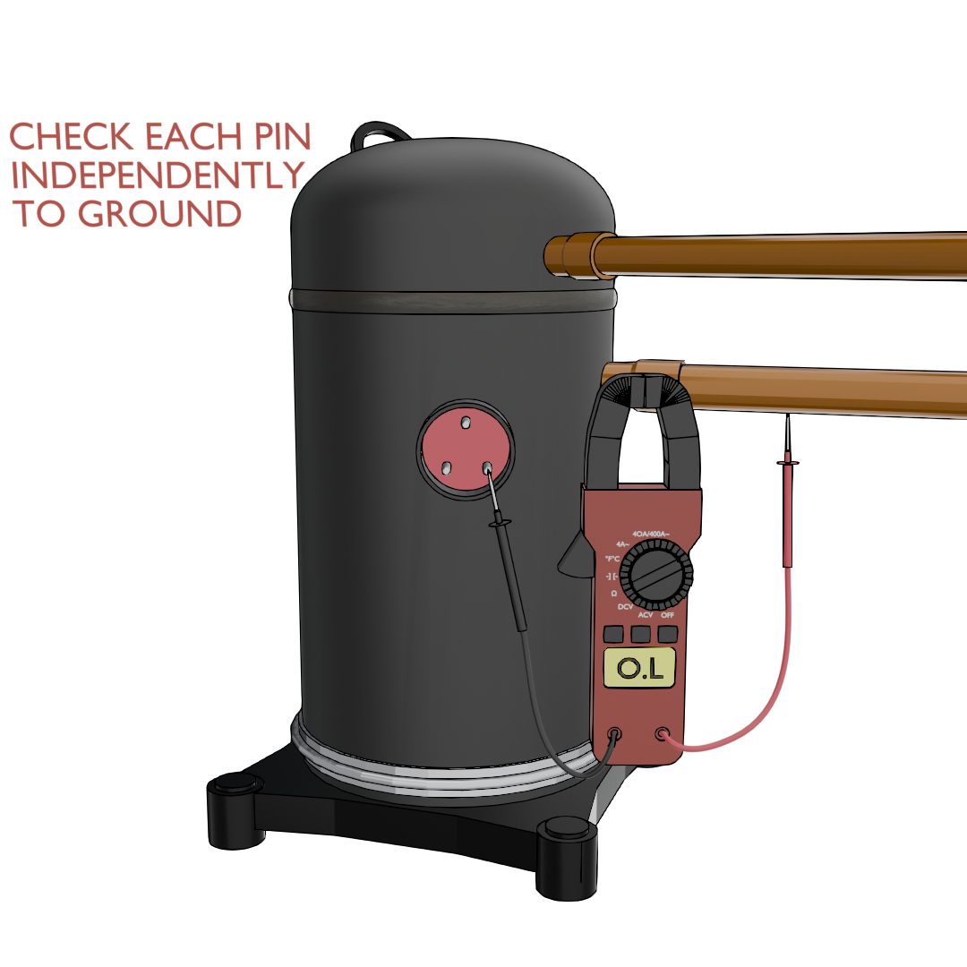
4. Check the compressor terminals for a short to ground.
Measure the resistance from each compressor terminal (Common, Start, Run) to a clean ground point on the compressor chassis or copper pipe.
Any continuity or low resistance reading to ground? The compressor is shorted to ground and has failed. You have confirmed the diagnosis.
No reading to ground (OL)? The compressor windings are not shorted to ground. The short likely exists elsewhere. Check other components:
- Condenser fan motor
- Crankcase heater wiring
- Any other wiring in the high-voltage circuit
AVOID THESE TOOLS FOR CONDEMNING
Do not use a megohmmeter (megger) to condemn a modern scroll compressor. Per Copeland's AE-1294 bulletin, a scroll can read as low as 0.5 MΩ and still be perfectly fine. Factors like refrigerant in the oil and winding temperature can give false “bad” readings on a megger.
A standard ohmmeter test to ground is the correct method.
Step 3: Verifying Voltage & Components
If the breaker was not tripped, we need to confirm the compressor is receiving the correct power and that its supporting components are functional.
1. SHUT OFF ALL POWER and verify that the circuit has no power.
2. Inspect the “Big 3” electrical components:
Capacitor: Test the run capacitor. Is it within its rated MFD tolerance (+/- 5-6%)? A weak or failed capacitor will prevent the compressor from starting.
Contactor: Are the points pitted, burnt, or welded? Manually press the contactor; does it move freely?
Wiring & Plug: Carefully inspect the wiring. Look for burnt or loose connections, especially at the compressor plug and contactor lugs. A bad connection is a common point of failure.
3. If the components above are good, proceed to Step 4: Winding Resistance Test.
Step 4: Winding Resistance Test
This test checks for shorts or open circuits within the compressor's motor windings.
1. Ensure that the power is off and the compressor wires are disconnected.
2. Set your multimeter to measure ohms (Ω) on manual range.
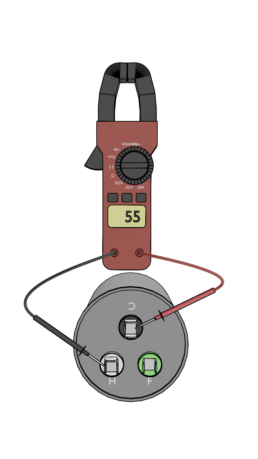
3. Measure and record the resistance between the three terminals.
- Common to Start = _____ Ω
- Common to Run = _____ Ω
- Run to Start = _____ Ω
4. Analyze the readings:
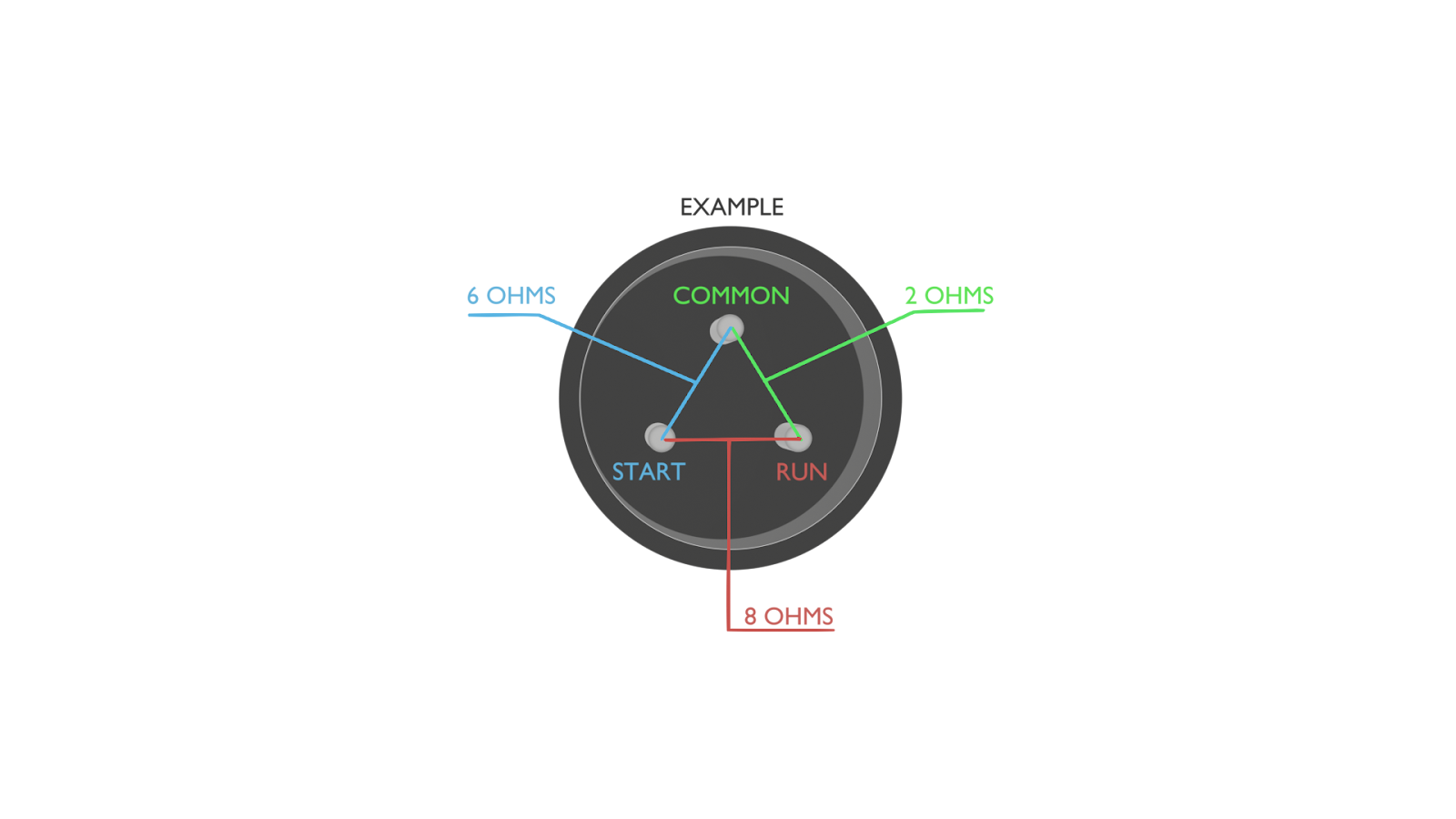
Check the formula: (Common to Start) + (Common to Run) = (Run to Start). Do your readings add up?
- If YES: The windings are likely okay.
- If NO: You likely have a turn-to-turn short inside the compressor. The compressor has failed.
Check for an open winding: Do you get an OL (Over Limit) reading between any two terminals? This means the winding is broken internally. The compressor has failed.
Best Practice: Don't just rely on the formula. Use the Copeland Mobile app or manufacturer data to look up the exact winding resistance specifications for the specific compressor model you are working on. This is the most accurate way to verify your readings.
Part 2: Investigating the Cause of Failure (“The Why”)
Now that you've confirmed the compressor is bad, you must find out why it failed. Installing a new compressor into a faulty system will only lead to another failure.
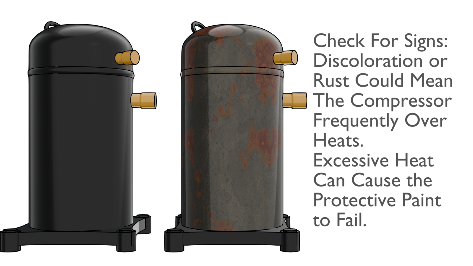
Step 5: Check for Signs of Overheating
Overheating is a slow death for a compressor, often caused by a low refrigerant charge, which leads to poor cooling and high head pressure.
Visual Inspection: Look for discolored or burnt paint on the compressor shell, especially near the top. This is a tell-tale sign of excessive operating temperatures.
System Check: Review the system's charge and operating conditions. Was the system running with a low charge? Was the condenser coil dirty or the fan failing, causing high head pressure?
Step 6: Check for Liquid Refrigerant Damage
Liquid refrigerant will destroy a compressor, which is designed to compress vapor only. This happens in two main ways: floodback and flooded starts.
Check for Floodback (Liquid in a Running Compressor): This is often caused by low or zero superheat. Investigate the metering device (TXV/piston) and evaporator airflow. Is the TXV bulb mounted correctly and insulated? Is the evaporator coil or filter clean?
Check for Flooded Starts (Liquid in an Off-Cycle Compressor): This happens when liquid refrigerant settles in the crankcase during shutdown and violently boils at startup, washing oil away from critical parts.
- Inspect the Crankcase Heater: Is it working? Is it wired correctly? A common mistake is miswiring a heater after replacing a single-pole contactor with a two-pole, rendering the heater useless.
- Evaluate System Design: Are there long refrigerant lines without proper traps? Is the system overcharged? These factors increase the risk of flooded starts.
Step 7: Check for Loss of Lubrication
Oil is the lifeblood of the compressor. Insufficient oil return leads to friction, overheating, and mechanical failure.
- Inspect Piping Practices: Are the line sets properly sized? Improper piping is a primary cause of poor oil return.
- Connect to Other Failures: Remember that flooded starts (Step 6) also cause oil loss as the foaming refrigerant carries oil out of the compressor.
Step 8: Check for System Contamination
Contaminants act like poison in a refrigerant circuit, leading to chemical reactions and physical damage.
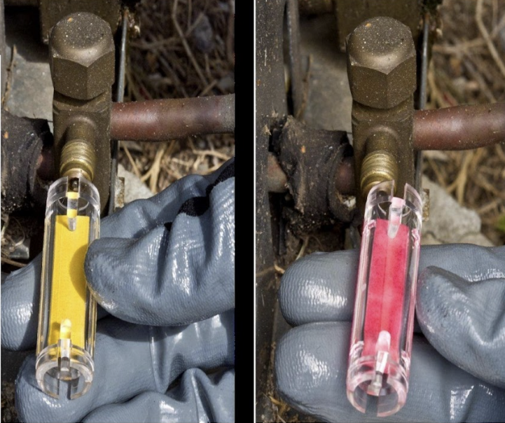
Perform an Oil and Acid Test: When you remove the compressor, take an oil sample. Is it dark or sludgy, or does it have a burnt smell? Use an acid test kit. If acid is present, a thorough system flush and the installation of a temporary suction line filter-drier are mandatory to protect the new compressor.
Identify the Contaminant:
- Moisture: The most common contaminant, leading to acid formation and copper plating.
- Non-Condensables (Air, Nitrogen): Increase head pressure and system temperatures.
- Solid Debris: Debris from a previous failure or installation can cause blockages and wear. Check the old filter-drier and screen at the metering device.
Part 3: Installing the New Compressor
A quality installation is the best guarantee for a long compressor life. Follow these best practices meticulously.
Step 9: Brazing Best Practices
Proper brazing prevents internal contamination and ensures strong, leak-free joints.
Purge with Nitrogen: Before brazing, you must remove the oxygen from the lines to prevent internal oxidation (black scale). Use the 3X pressurize-and-dump method:
- Pressurize the lines with dry nitrogen.
- Vent the nitrogen completely.
- Repeat this process at least three times.
Flow Nitrogen During Brazing: After the purge, flow nitrogen at a very low rate (2-3 SCFH) through the lines while brazing. Do not flow nitrogen directly through the compressor.
Use the Right Alloy: Compressor stubs are often copper-plated steel. If the copper plating burns away, you'll need a high-silver (e.g., 56%) flux-coated brazing rod to create a strong bond with the steel underneath.
Protect Components: Use wet rags or a heat-blocking putty (like Viper WetRag or HeatShield) to protect the compressor body paint, electrical terminals, and nearby components from heat damage.
Step 10: Leak Testing
Never skip a thorough leak test. Finding a leak now is far easier than coming back for a refrigerant leak call.
Nitrogen Pressure Test: After the joints have cooled, pressurize the system with dry nitrogen to the pressure specified on the unit's data tag. Let it sit and monitor for any pressure drop, which indicates a leak.
Bubble Test: Apply a quality leak reactant solution (like Refrigeration Technologies Big Blu) to all brazed joints and fittings. Use a mirror to inspect hard-to-see areas. Watch carefully for any bubbles or foam “cocoons” to form, which will reveal even the smallest leaks.
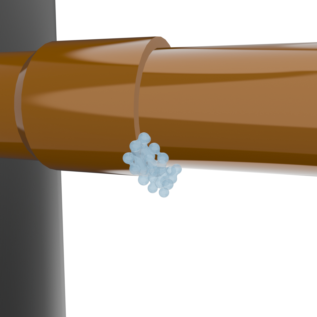
Microbubbles can go unnoticed without careful inspection
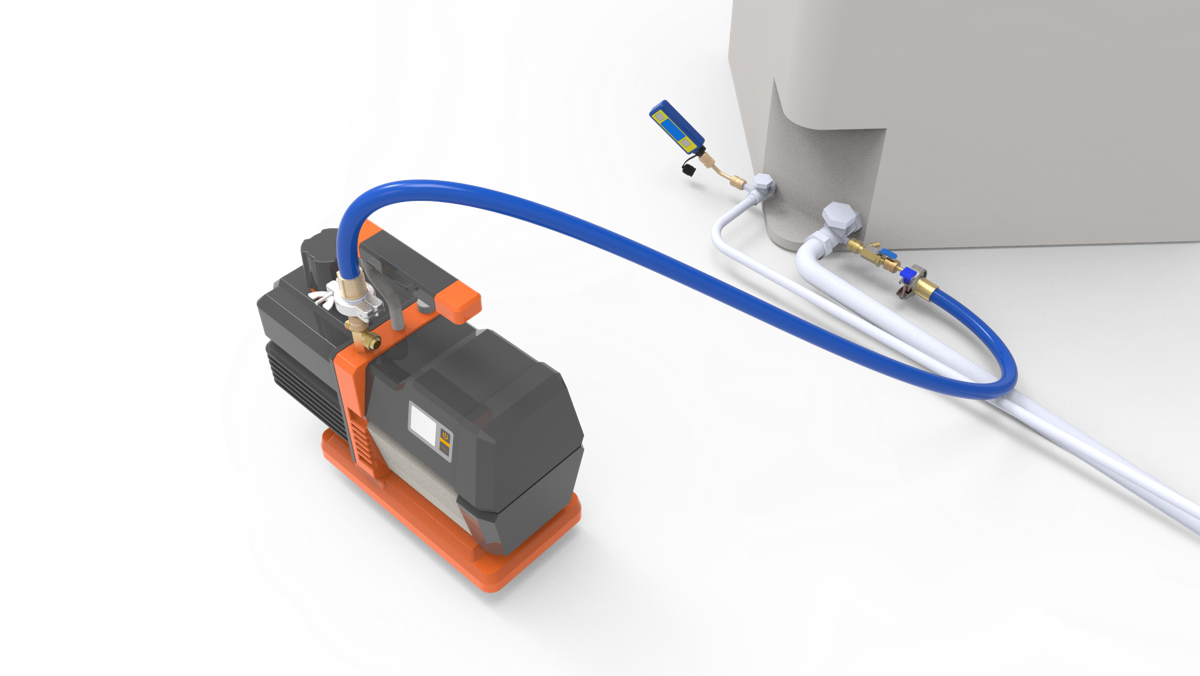
Step 11: Evacuation and Decay Test
A proper evacuation removes moisture and non-condensables, ensuring system efficiency and longevity.
Pull a Deep Vacuum: Evacuate the system to below 300 microns.
Perform a Decay Test: Isolate the system from the vacuum pump. The vacuum level should not rise above 500 microns after holding for at least 10 minutes.
Troubleshoot a Failed Test: If the vacuum rises quickly or goes above 500 microns, you either have a leak or remaining moisture in the system. If it jumps past 1000 microns, you most likely have a leak that needs to be found and repaired.
Step 12: Wiring and Final Electrical Checks
Incorrect wiring can damage the new compressor or prevent it from starting.
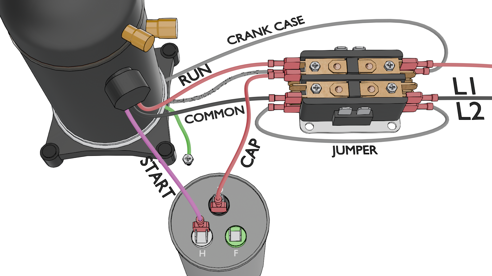
Correct Terminal Wiring:
- The compressor's Run winding connects to one side of the contactor.
- The run capacitor's “C” terminal is fed from that same side of the contactor.
- The compressor's Common winding is fed from the other side of the contactor.
- The compressor's Start winding connects to the “Herm/H” terminal on the run capacitor.
Replace Components:
- Always replace the run capacitor with a new one when replacing the compressor.
- Always replace the compressor terminal plugs. Be gentle when tightening connections on the glass Fusite terminals to avoid causing damage.
- Remove any aftermarket hard start kits. Only install a factory-approved start assist if the manufacturer requires it, especially on a system under warranty.
Part 4: System Charging and Final Checks
The final steps involve carefully charging the system and verifying its operation to ensure the new compressor starts its life under ideal conditions.
Step 13: System Charging
Correctly charging the system is critical to prevent a repeat failure from an overcharged or undercharged condition.
Initial Holding Charge: Begin by introducing a partial charge into the liquid line with the system off. Place the refrigerant cylinder on a scale and add refrigerant until the pressures equalize. This prevents liquid from slugging the compressor on startup.
Final Vapor Charging: Once the compressor is running, slowly add the remaining refrigerant as a vapor into the suction line. Charge to the manufacturer's specifications using the superheat, subcooling, or weigh-in method. Be patient, especially on systems with an accumulator, to allow any liquid to fully vaporize before entering the compressor.
Verify the Charge: Always weigh the charge recovered from the old system and compare it to the nameplate value. This can help identify pre-existing charge issues. If the system was undercharged, investigate for leaks. If it was overcharged, look for potential refrigerant restrictions or airflow problems that may have led to a misdiagnosis.
Step 14: Post-Installation Commissioning & Verification
After installation, verify that the system is operating as intended and create a performance baseline. This ensures the root cause of the failure was fixed and provides a reference for future service calls.
Confirm System Airflow: Low airflow is a major cause of compressor failure. Confirm the actual CFM using a tool like a TrueFlow grid, not just by measuring static pressure. Investigate and correct any issues like dirty filters, blocked coils, or ductwork problems.
Clean and Inspect: Ensure the condenser and evaporator coils are clean, and install new air filters.
Verify Operational Parameters: Allow the system to run and stabilize before taking readings.
- Check superheat at both the evaporator outlet and the compressor inlet.
- Check subcooling at the condenser outlet.
- Measure suction and head pressures.
- Measure delta T across the evaporator coil.
- Check the discharge line temperature about six inches from the compressor outlet. High temperatures can indicate oil breakdown or other internal issues.
Create a Full System Profile: Record all operating temperatures, pressures, and electrical readings (amps, volts). Using a tool like measureQuick can help streamline this process and provide a comprehensive report.
Part 5: Protective Devices & Electrical Upgrades
Consider valuable add-ons that protect the new compressor and improve system reliability.
Step 15: Consider Protective Devices & Electrical Upgrades
Surge Protection: Install surge protection to prevent damage from transient voltage spikes. While standard single-phase compressors are robust, power surges can still cause damage.
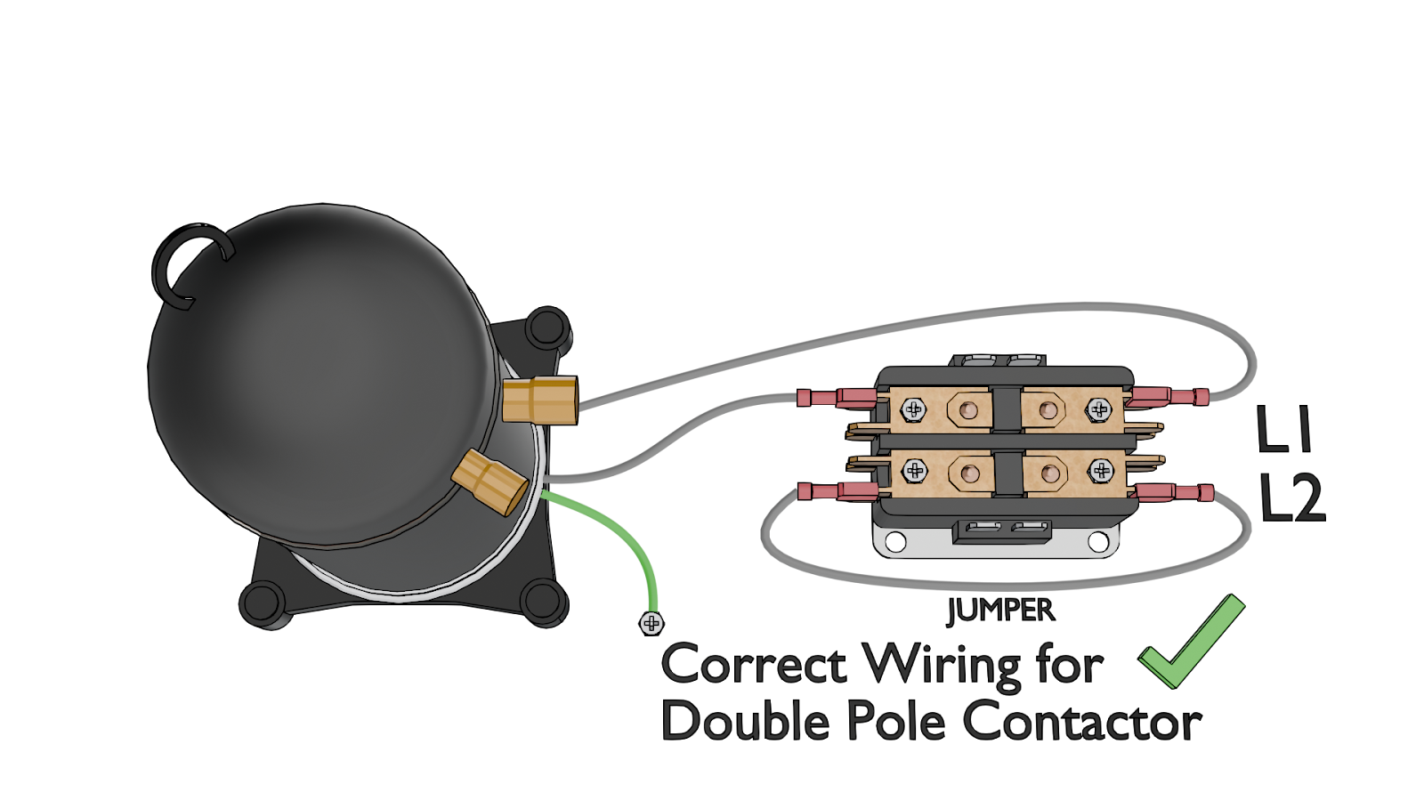
Contactor Upgrade: Discuss upgrading to a premium contactor like the White-Rodgers SureSwitch. These offer benefits such as brownout protection, built-in short-cycle delays, and sealed contacts that are less prone to failure due to insects or pitting.
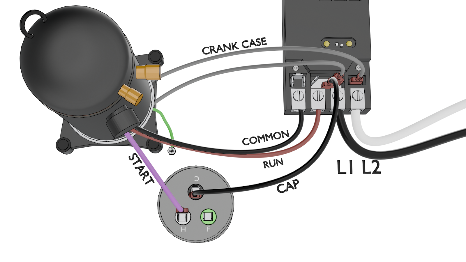
Note: the image above only represents the wiring required for the compressor and crankcase heater. It does not show the fan or low-voltage wiring.
Overvoltage Protection: For sites with consistent steady-state overvoltage problems, a device like the DITEK KoolGuard2 can be an option, though it provides the most value for systems with inverter drives or VFD motors.
Part 6: Tools for the Job
To replace a compressor successfully, you’ll need the right tools. Here is a list of tools and materials needed for a residential single-phase compressor installation. (We also have a PDF version at http://www.hvacrschool.com/compressor-replacement-tool-checklist.)
Testing & Diagnostic Tools
- Acid test kit
- Leak detector
- Scale (for weighing old and new compressors and refrigerant)
- Micron gauge
- measureQuick or a similar system profiling tool
- TrueFlow grid (or similar airflow measurement tool)
- Multimeter
- Manifold gauge or probe set
- Thermal imager (optional)
- Heat gun (optional)
Recovery & Brazing Equipment
- Recovery machine
- Recovery tank
- Vacuum pump
- Nitrogen cylinder and regulator
- Brazing torch/kit
- 15% silver phos brazing rods
- 56% flux-coated high-silver brazing rods
- Heat shields (such as the Viper WetRag HeatShield)
- Wet rags
Piping & Fittings
- Suction line filter drier (HH model for burnouts)
- New liquid line filter drier
- Ball valves (for isolating driers)
- Standard piping (to replace temporary suction line filter-drier)
- Various fittings and piping as needed
- Copper pipe cutter, deburring tool, and tubing bender
Replacement Components & Electrical
- New compressor
- Replacement plugs and connectors for compressor terminals
- Factory-approved hard start kit (if specified)
- Run capacitor
- Contactor (or upgrade)
- Large gauge wire (if needed for rewiring)
- Crankcase heater
- Wire strippers, crimpers, wire nuts
Safety & Protective Gear
- Safety glasses
- Gloves
- Other standard PPE
Additional Tools & Materials
- Refrigerant
- New air filters
- Surge protector (recommended)
- Ditek KoolGuard (optional)
- x2 Vacuum hoses (one large diameter)
- x2 Valve core removal tools
- Dedicated recovery hose
- Screwdriver set
- Adjustable wrenches
- Pliers
- Tubing benders
- Level
- Compressor lifting tool
- Zip ties
- Electrical tape
- Sandpaper or emery cloth
- Leak detection bubbles or spray
- System labels
- Cleaning rags/towels
- Digital thermometers/probes
- Service valve wrench
Conclusion: A Recipe for Success
Replacing a compressor is more than just a mechanical swap; it's a complete system overhaul. By following this checklist, you move beyond simply fixing the immediate problem. You become a system detective, a skilled installer, and a proactive technician.
This methodical approach—from confirming the failure and diagnosing the root cause to performing a meticulous installation and commissioning—is the difference between a callback and a callback customer. Taking the time to do it right ensures the new compressor has the best possible chance at a long, efficient life, ultimately providing the most value and reliability for your customer.
—JD Kelly
 Related Tech Tips


Comments
To leave a comment, you need to log in.
Log In