
Get Tech Tips
Subscribe to get free tech tips.
Confirming Liquid Levels with a Little Thermodynamics

Maintaining the correct vapor-liquid refrigerant balance is crucial for air conditioning and refrigeration system performance.
Longer line sets hold more refrigerant, which increases the risk of liquid accumulating in the suction line or entering the compressor during off-cycles.
Heat pumps are one common application that requires additional measures. Refrigerant flow reverses during heating, turning the outdoor coil into the evaporator. In extremely cold weather, complete vaporization can be challenging. The suction accumulator mitigates potential liquid floodback, a common issue during defrost cycles.
Years ago, an old-time refer tech taught me how to use a torch to find the liquid level in a receiver, and this tech tip is an updated version of that same concept. This time, we're confirming liquid levels in accumulators with a heat gun and a thermal imager.
Accumulators
At the heart of the HVAC system lies the compressor, and for the most part, it will run and do its job relatively maintenance-free for many years. However, the compressor has a major nemesis: liquid.
Liquids do not compress very well, so getting liquid refrigerant into a vapor compressor can have damaging effects. That’s where the accumulator steps in. The accumulator is often overlooked and misunderstood, but it plays a crucial role; it acts as a reservoir to collect liquid refrigerant and prevent it from entering the compressor.
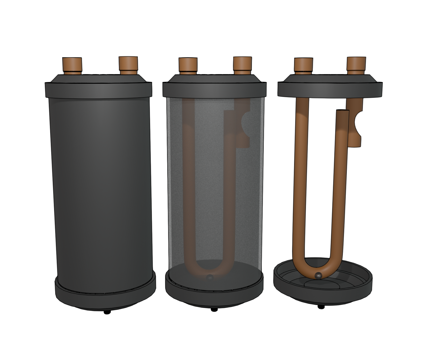
The accumulator is basically a steel tank located in the suction line of an air conditioning or refrigeration system, just before the compressor. Its sole purpose is to prevent liquid refrigerant from entering the compressor by allowing the heavier liquid refrigerant to pool at the bottom of its tank. The design is very simplistic, utilizing an input connection that allows the refrigerant to enter the tank, where the liquid will fall to the bottom and be trapped.
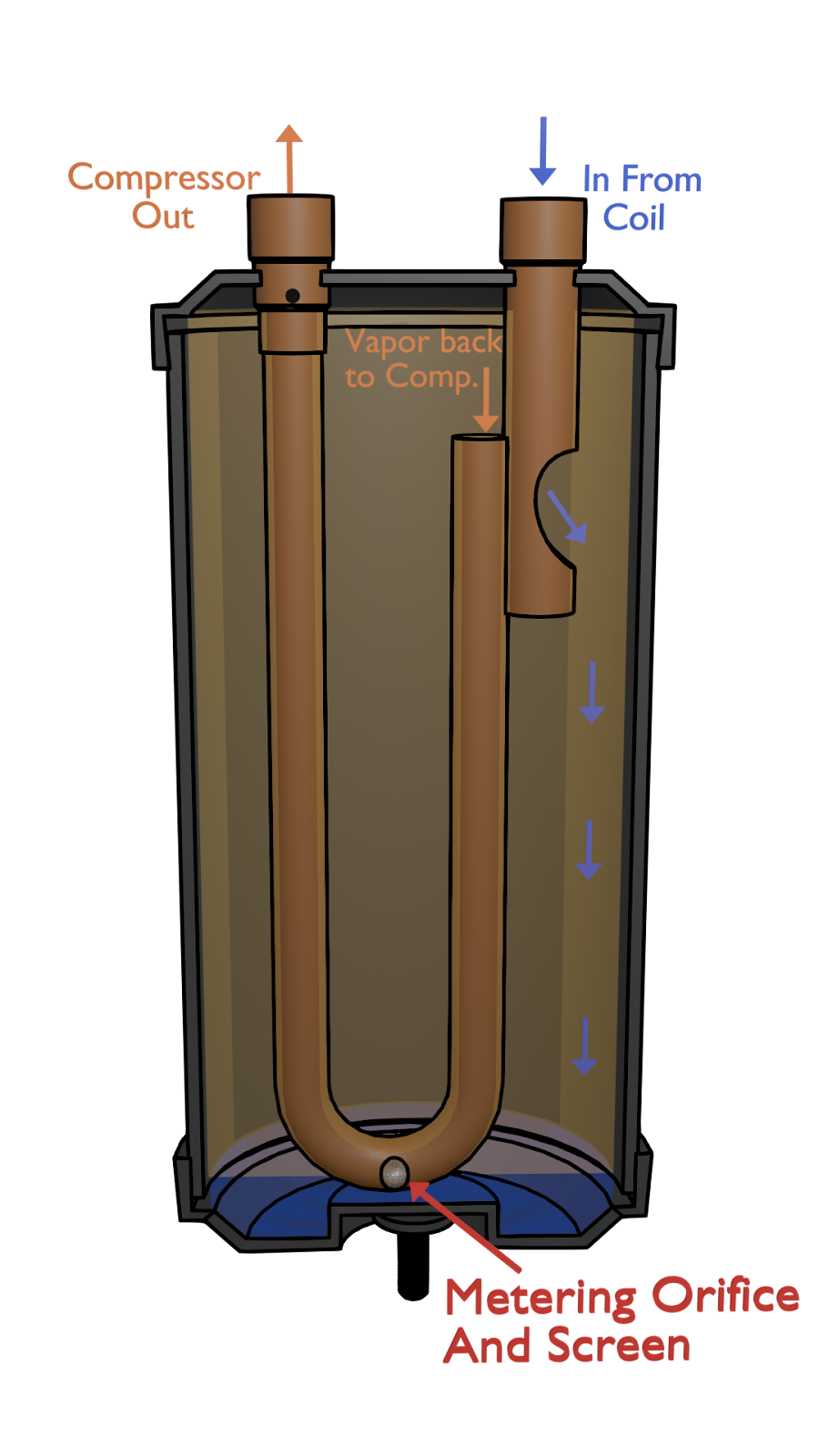
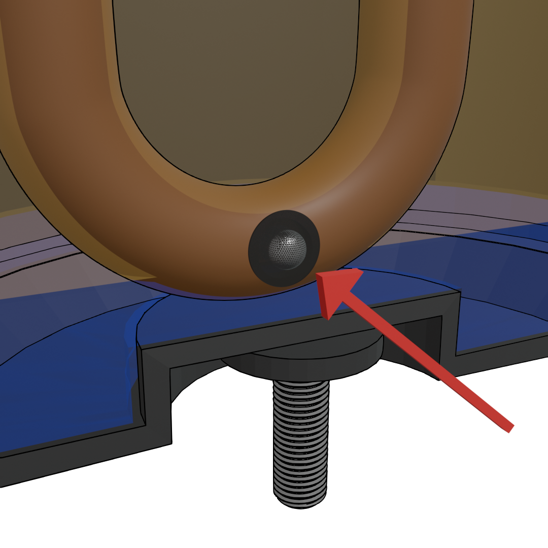
An accumulator tank features a U-shaped tube extending to the reservoir's base, designed with two openings. The upper opening serves as the vapor passage to the compressor. A second, lower opening, often referred to as a metering orifice, is positioned at the tube's bend. This second hole is intended to remain submerged in the liquid. Its function is to draw oil into the tube and return it to the compressor for lubrication purposes.
Receivers
Receivers and accumulators are frequently mistaken for each other, but their functions are almost opposite. The accumulator, placed on the suction or low side, prevents liquid refrigerant from advancing to the compressor. The primary job of a receiver, located on the liquid line on the high side, is to store excess liquid refrigerant. It acts as a reservoir, ensuring that a solid, bubble-free column of high-pressure liquid refrigerant is always available to feed the metering device (like a TXV). This function is crucial in systems where the refrigerant demand fluctuates with the heat load, like market refrigeration.
Confirming Liquid Levels Inside These Devices
Understanding how accumulators and receivers function will help you better troubleshoot efficiency problems and operational failures due to refrigerant charge-related issues.
However, once the function of the tanks is understood, figuring out how to test them is a separate challenge. But let's first look at why it is beneficial to test them in the first place, and then we’ll go over some techniques on how to test them.
Why Check the Liquid Level in the Receiver?
Checking the liquid level in a receiver is primarily about verifying the correct refrigerant charge and ensuring the system has enough refrigerant to operate efficiently.
Indicator of System Charge
A receiver is designed to store excess liquid refrigerant. A sight glass is often installed in the liquid line just after the receiver. If this sight glass is full of bubbles (a condition called “flashing”), it indicates there isn't enough liquid refrigerant leaving the receiver. Flashing may be an indication of an undercharged system, but it should not be the only thing you check to confirm an undercharged system. It can also represent a hot pull down where the TXV is wide open, or even a condenser pressure regulator (head master) that is cycling. It can sometimes even be an indication of mixed refrigerants. Many systems have been overcharged by using a sight glass alone to confirm undercharge. By confirming a low level in the receiver, a technician can confidently diagnose a refrigerant leak or an improper initial charge.
Ensuring a Full Column of Liquid
The expansion valve (especially a TXV) requires a full column of bubble-free liquid to work properly. If vapor is allowed to enter the expansion valve, it dramatically reduces its capacity and starves the evaporator. This leads to poor cooling, high superheat, and overall inefficiency. Checking the level ensures the receiver is doing its job of providing this essential liquid supply.
Diagnosing Overcharge
While less common, an extremely full receiver, especially when combined with other symptoms like high head pressure, can indicate that the system is overcharged.
Note: A liquid receiver should never be more than 80% full during a pump down. There are situations when the factory-installed receiver is too small for long lineset applications.
Why Check the Level in an Accumulator?
Checking the level in an accumulator is all about protecting the compressor and diagnosing potentially catastrophic system faults. Under normal operation, an accumulator should contain very little liquid.
Preventing Compressor Slugging
The most important reason to check the liquid level in an accumulator is to ensure that it isn't full or “flooded” with liquid refrigerant or oil. When the system goes into an automatic pump down, the receiver should hold the entire charge and still have 20% additional capacity for safety and expansion of temperature changes. Overcharge can cause the system not to pump down, or the liquid receiver may even rupture. If the accumulator fills up completely, it can no longer do its job. Liquid refrigerant will then be drawn directly into the compressor. Liquid refrigerant washes oil away from the bearings and moving parts, causing premature compressor failure. Liquid doesn’t compress very well, so an event known as slugging will occur, which can cause damage to the compressor.
Diagnosing Upstream Problems
A high liquid level in the accumulator during operation is a major red flag that something is wrong upstream. A technician would check this to diagnose issues such as:
- Airflow:
- Poor airflow (bad airflow, undersized or blocked ducts, dirty blower wheel, wrong motor, or cut-off plate position)
- Restrictive or undersized filter
- Undersized or blocked return in the summer
- Coils:
- Dirty indoor or outdoor coil
- Coil blocked by structure, recirculated air, or even snow buildup
- Defrost:
- Faulty defrost or defrost settings
- Heat Exchanger:
- Dirty secondary heat exchanger
These reduce the heat necessary to boil the refrigerant completely into superheated vapor:
- A failed or oversized expansion valve that is allowing too much liquid refrigerant into the evaporator
- Poor evaporator performance is caused by dirty coils or other causes of low airflow, which prevent the refrigerant from boiling into a vapor
- A significant system overcharge, where the excess refrigerant has nowhere else to go and backs up into the accumulator
Verifying Oil Return
Accumulators are also responsible for metering trapped oil and returning it to the compressor. If a technician suspects an oil return problem (which can also destroy a compressor), checking for an abnormally high level of oil in the accumulator is a key part of the diagnostic process.
Testing
To test the contents of the sealed accumulator or receiver tank requires a little bit of ingenuity and a basic understanding of the 2nd law of thermodynamics and thermal capacitance. The 2nd law of thermodynamics involves the principle that heat will always flow from a region of higher temperature to a region of lower temperature. Thermal capacitance relates to a substance's ability to absorb and store heat.
The premise of the testing involves taking advantage of the fundamental differences in heat absorption and release between liquid and gas. Liquids have a higher thermal capacitance, meaning that they absorb and release heat much more slowly than a vapor or gas. This understanding will give us the opportunity to peer into the sealed tank by leveraging what we know about heat absorption.
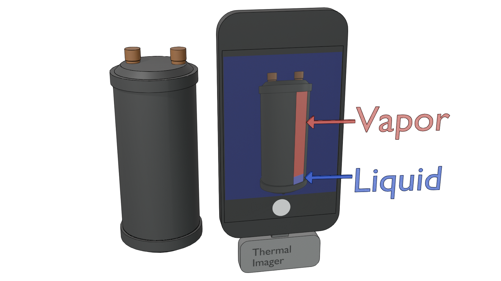
To do this, we will need a heat gun and a thermal imager. By briefly and quickly warming a vertical section of the tank with a heat gun, you create a temporary temperature difference between the portion of the tank containing liquid and the portion containing vapor. The area of the tank in contact with the liquid will remain cooler for a longer period, while the section with vapor will heat up more quickly.
Immediately after applying heat, view the heated area with a thermal imager. The thermal imager will display a clear visual representation of the temperature differences. The area of the tank with liquid will appear cooler, often represented by darker bluish colors on the thermal imager. On the other hand, the section of the tank containing vapor will appear warmer and be represented by lighter reddish colors.
Tips for Accurate Readings
This technique does require a degree of care and skill. One of the most important things to think about when using this method is applying the heat evenly. Heating one section up for too long will affect the final readings.
You’ll also want to move quickly to capture the temperature difference after applying the heat. After you have applied the heat, it is important to transition to the thermal imager as quickly as possible, as the heat is only temporary and will soon dissipate.
We’ll also have to consider existing temperatures. The tank's existing temperature will dictate the amount of heat that you will add to it. A tank that is relatively cool won’t require much heat to be added to reveal a clear thermal image. However, a tank that’s already quite hot might make the color differences in the thermal image less clear. The key is to have a sharp contrast in temperature between the liquid and the vapor.
Conclusion
This technique for confirming liquid levels in accumulators is not something that a technician will find themselves using on a daily basis. However, having a grasp on it not only gives you an extra tool in your arsenal of diagnostic tests, but it also helps you better understand concepts like heat transfer and thermal capacitance.
—JD Kelly
 Related Tech Tips


Comments
To leave a comment, you need to log in.
Log In