
Get Tech Tips
Subscribe to free tech tips.
Upgrading a Single-Pole Contactor with a SureSwitch: Using a Wiring Diagram

Along the path to becoming a great HVAC technician lies the dreaded wiring diagram. It's meant to be a helpful map of the equipment's electrical system, but with its crisscrossing lines and cryptic symbols, it often feels more like a barrier than a guide.
If this sounds familiar, you're not alone. But what if you could look at that drawing and see a clear, physical map of the unit in front of you? And what if you could use that map to not only troubleshoot but also perform upgrades with confidence?
This guide will do just that. We'll use the most common type of diagram—the pictorial diagram—to walk step-by-step through a real-world task: upgrading a standard single-pole contactor to a Copeland SureSwitch™ solid-state contactor. By the end, you'll not only understand how to perform the upgrade, but you'll have used a pictorial diagram to do it, turning that confusing drawing into your most valuable tool.
The Foundation: Why the Diagram is Your Guide
First, let's be clear: a pictorial wiring diagram is a visual map of the equipment's physical layout and connections. For this project, it's our instruction manual. It will help us:
- Identify the physical location of components.
- Trace the path of the actual wires.
- Ensure the new, aftermarket part is installed correctly and safely.
While other diagrams exist, the pictorial is our focus here because it directly mirrors the unit you're working on, making it perfect for hands-on tasks.
Case Study: Upgrading a Single-Pole Contactor to a Copeland SureSwitch
Our task is to replace a standard, mechanical single-pole contactor with a modern, electronic Copeland SureSwitch. A single-pole contactor only opens one leg of the high-voltage power to the compressor, while the other leg is always connected. The SureSwitch is a two-pole, solid-state device that offers benefits like brownout protection, short-cycle timing, and a microprocessor-controlled switch, making it a popular reliability upgrade.
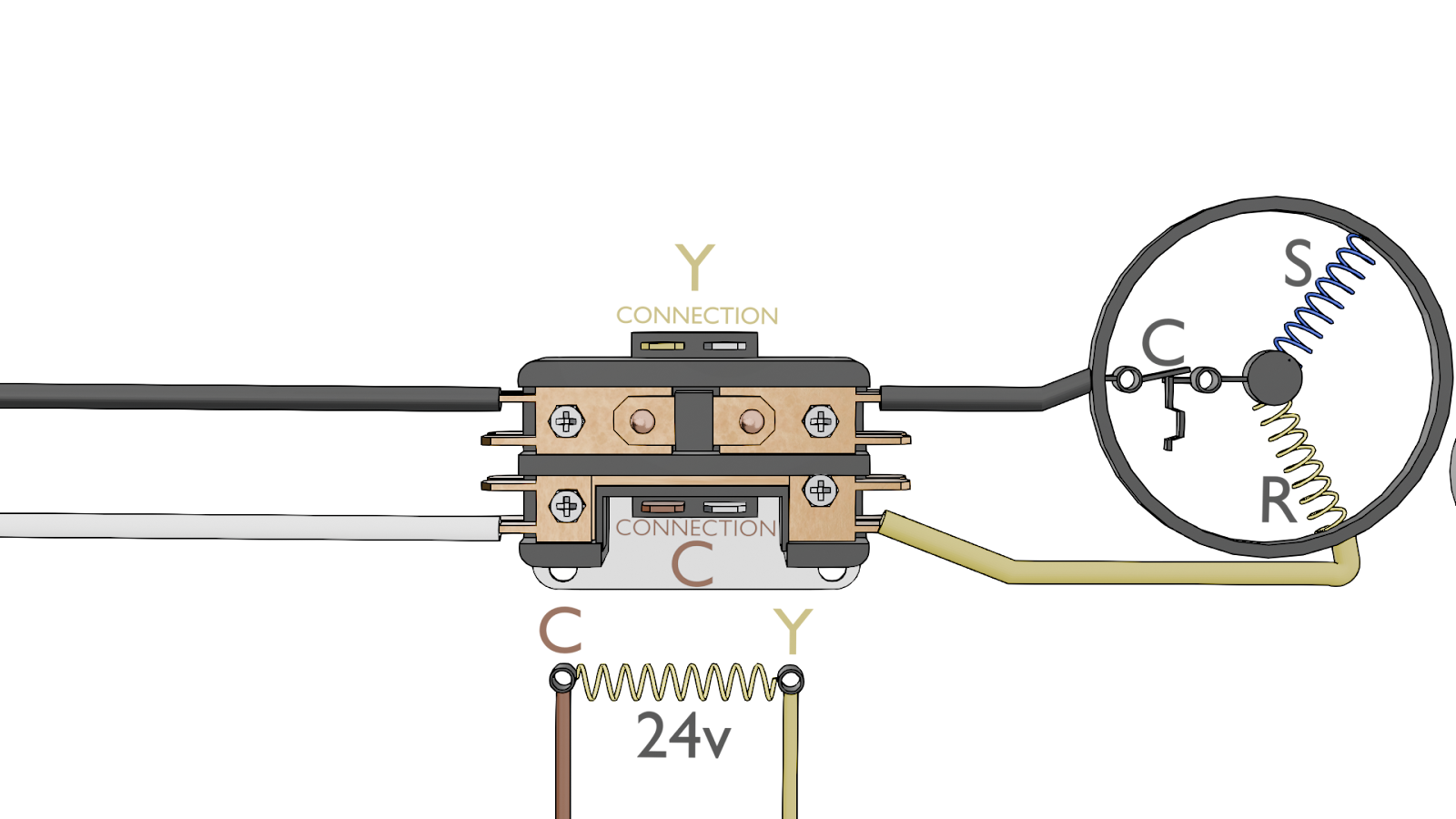
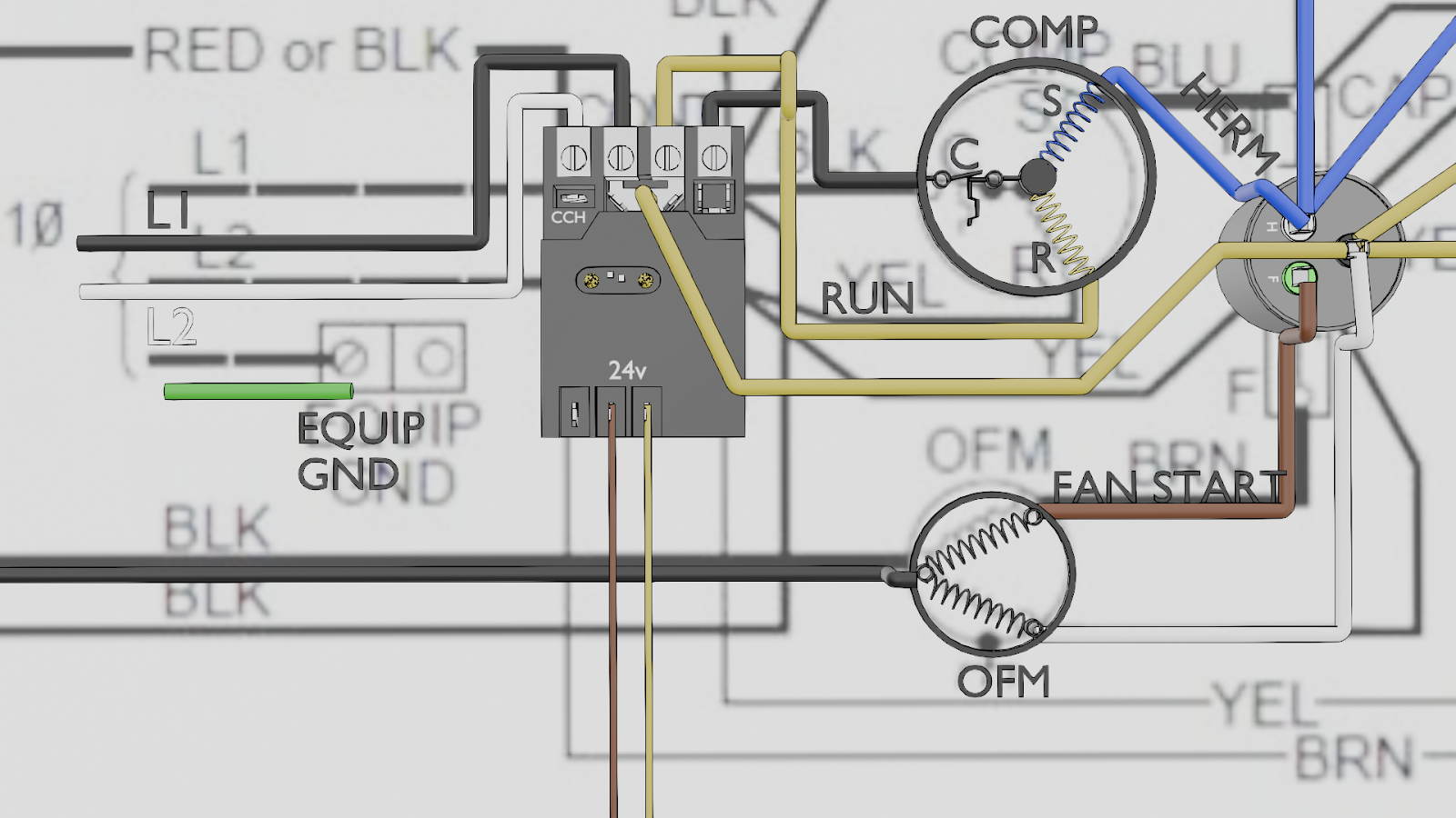
Step 1: Analyze the Original Circuit with the Pictorial Diagram
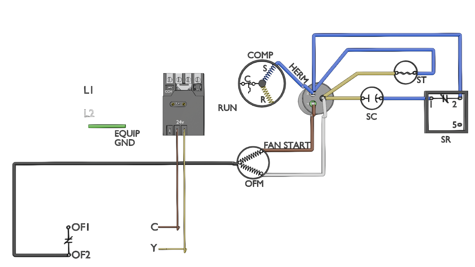
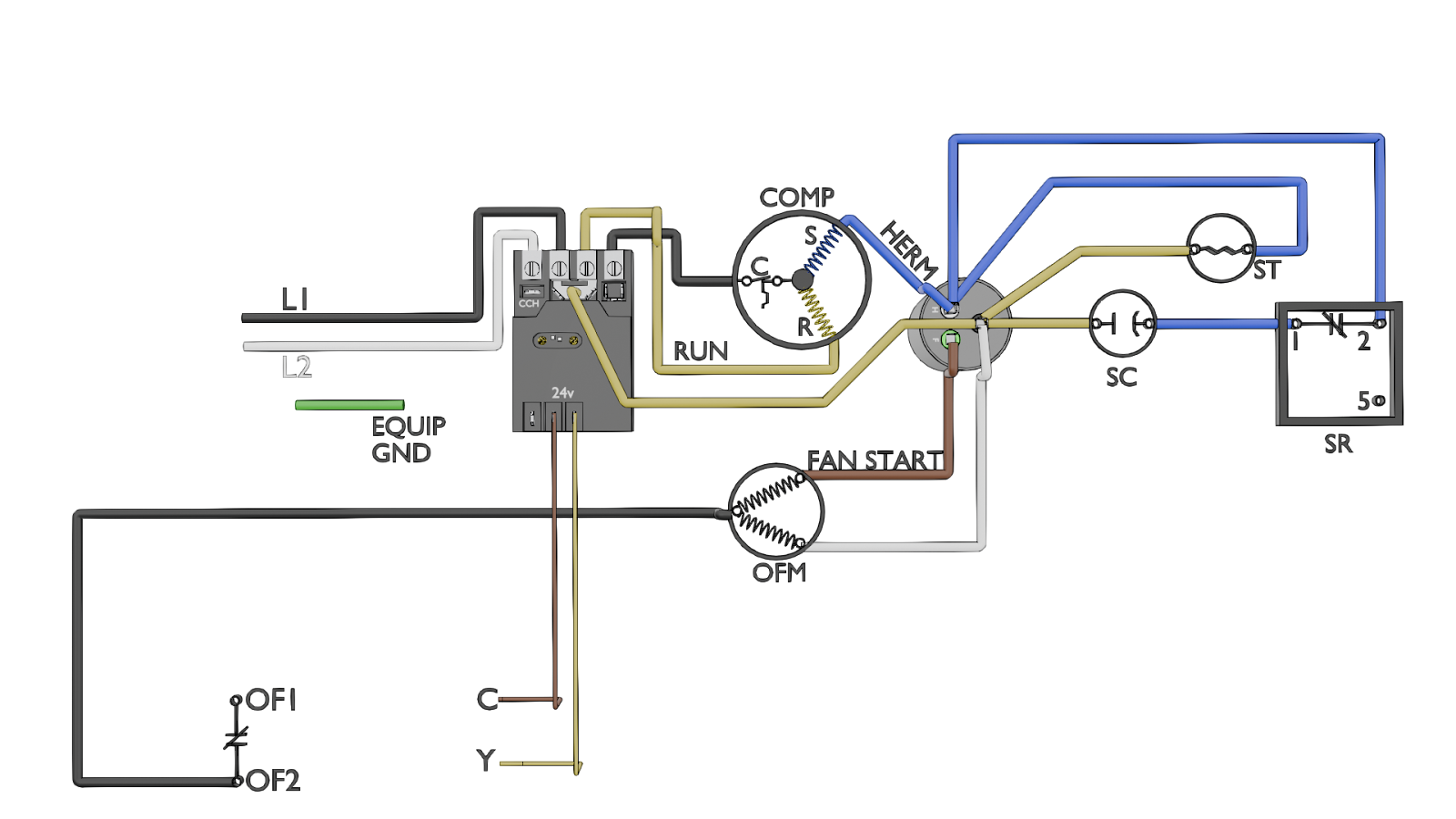
Before we touch a single wire, we must understand the existing layout. Let's look at a typical pictorial diagram of an air conditioner's control panel.
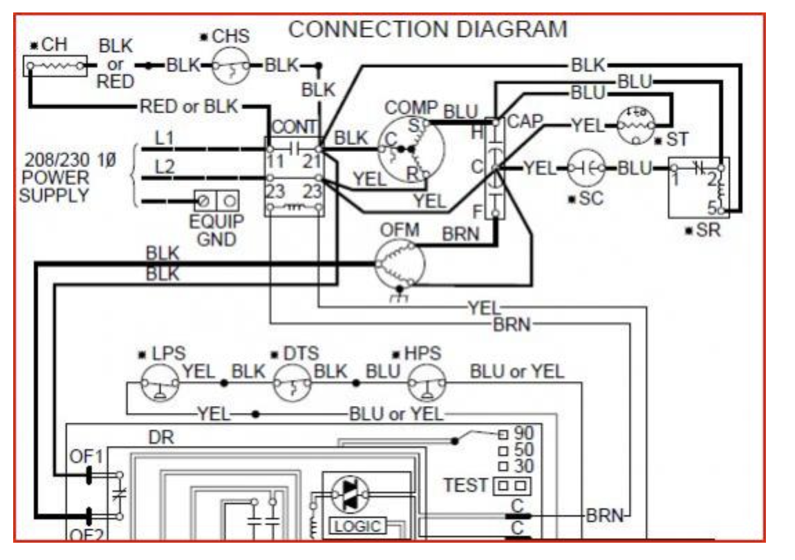
Reading the Diagram:
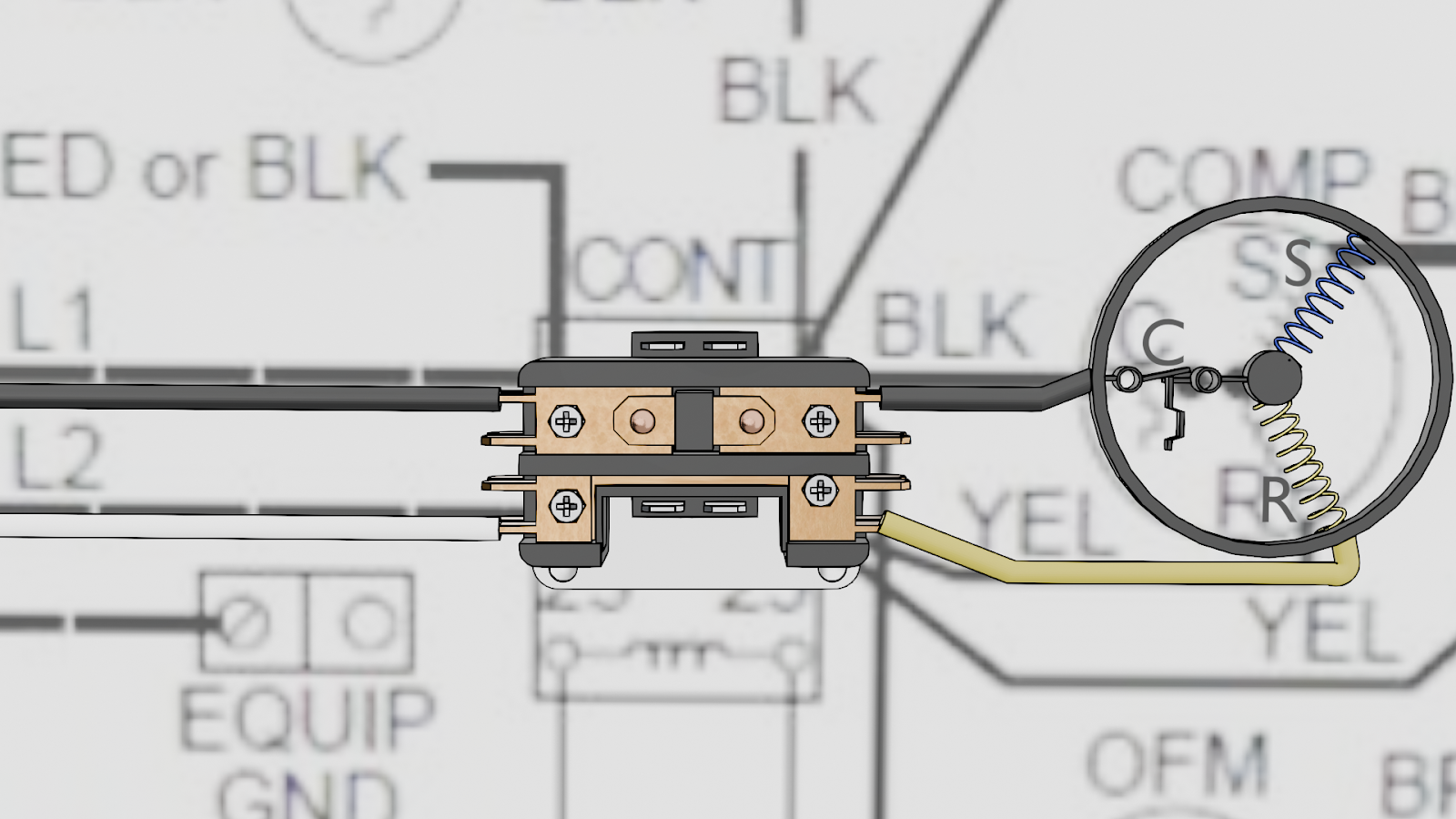
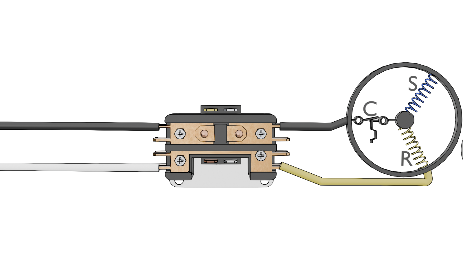
1. Trace the High Voltage:
- Find the incoming power lines, L1 and L2.
- The diagram shows L1 connecting to one side of the contactor. A corresponding wire, T1, leaves the other side and goes to the compressor.
- Now, trace L2. The diagram shows it connecting to the L2 terminal of the contactor. Notice that this terminal is directly connected to the T2 terminal of the contactor terminal block and goes directly to the compressor; this leg of power is continuous and cannot be switched on and off. This visual confirmation is how we know it's a single-pole contactor.
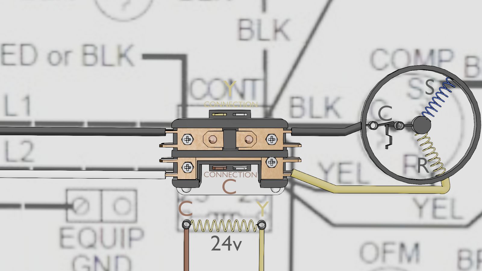
2. Trace the Control Voltage: Locate the small-gauge wires connected to the sides of the contactor coil. The pictorial diagram shows these wires coming from the thermostat cable. These are the 24V wires (Y and C) that pull the contactor's plunger in when the thermostat calls for cooling.
Step 2: Plan the Upgrade by Comparing Components
Now, let's look at our new part. The SureSwitch has different terminals because it has more features.
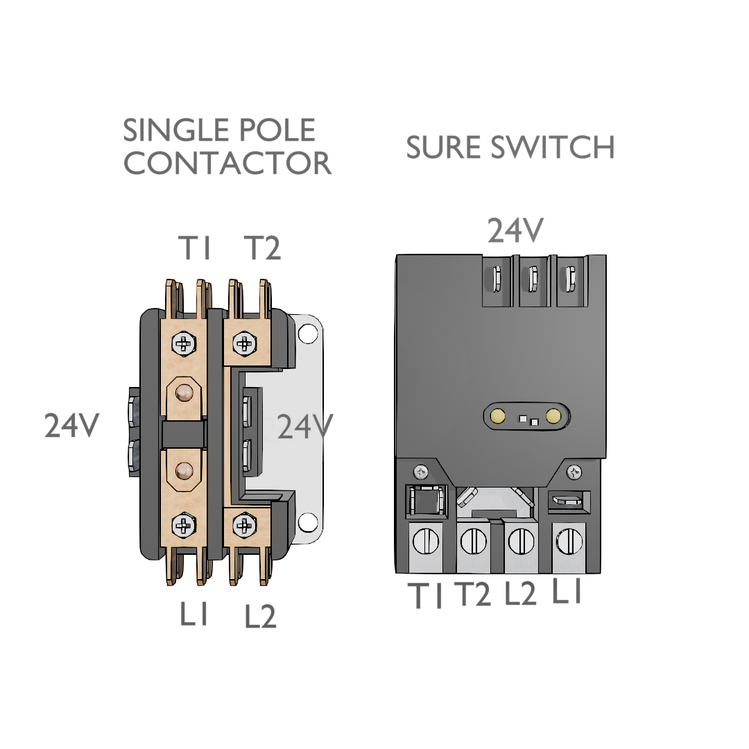
Old Contactor Terminals:
- Two coil terminals (for the 24V Y and C wires)
- L1 and T1 (for the switched high-voltage leg)
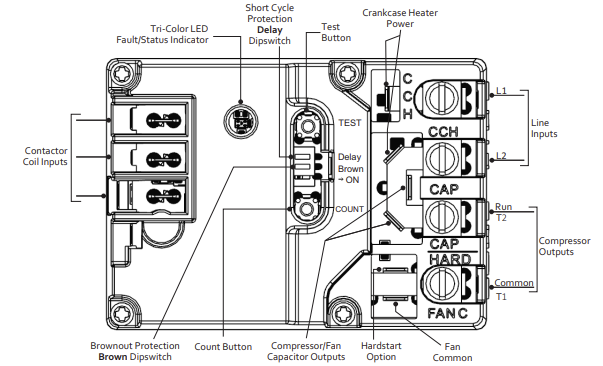
New SureSwitch Terminals:
- Y and C named contactor coil inputs.
- L1 and L2 (for the incoming high-voltage power)
- T1 and T2 (for the outgoing high-voltage power to the load/compressor)
- T2/CCH (A dedicated terminal for the Crankcase Heater)
- CAP (A dedicated terminal for capacitor wire)
- Fan Common (A dedicated terminal for fan common)
- Crank Case Heater (Dedicated terminals for the crank case heater)
Our job is to map the wires from the old setup to the new one. The SureSwitch needs a constant 24V common (C) to power its internal electronics.
Step 3: Step-by-Step Installation Using the Diagram
SAFETY FIRST: Disconnect all high-voltage and low-voltage power to the unit and verify that there is no power before beginning.
- Label the Wires: Using the pictorial diagram as your guide, label the physical wires in the unit so that you don't lose track of them. Additionally, take photos for reference.
- Remove the Old Contactor: Carefully disconnect the labeled wires and unscrew the old contactor from the unit.
- Mount the SureSwitch: The back plate of the SureSwitch is removable for mounting.
- Connect the Wires: This is where referencing the diagram pays off.
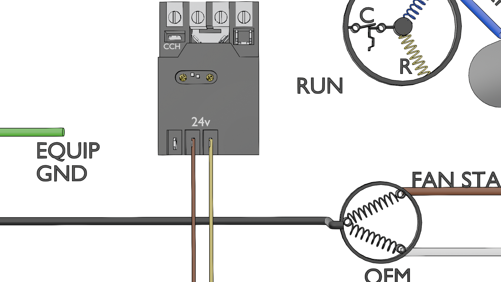
Control Voltage: Connect the thin thermostat wires to the Y and C terminals on the SureSwitch.
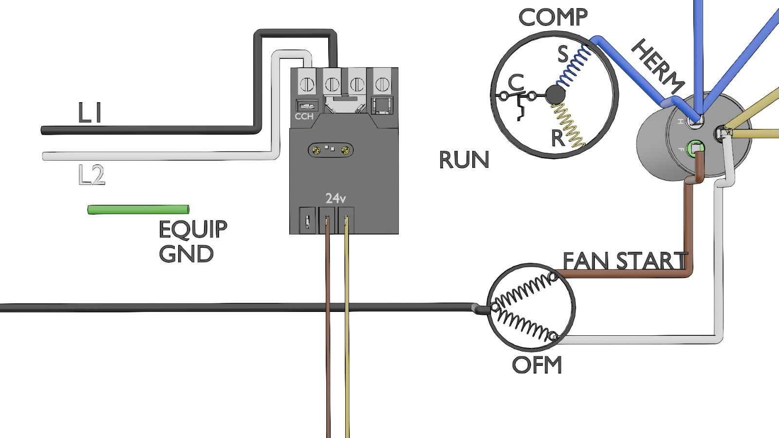
Line Voltage: Connect the main L1 and L2 wires to the SureSwitch. You are now feeding both legs of the 240V power into the new contactor.
Line 1
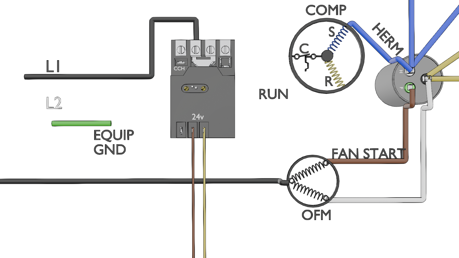
Line 2
Load Voltage: Connect the T1 wire (going to the compressor) to the T1 terminal. Connect the T2 wire (also going to the compressor) to the T2 terminal. Now, both legs of power are being sent from the SureSwitch to the compressor.
T2 to Compressor Common
T1 to Compressor Run
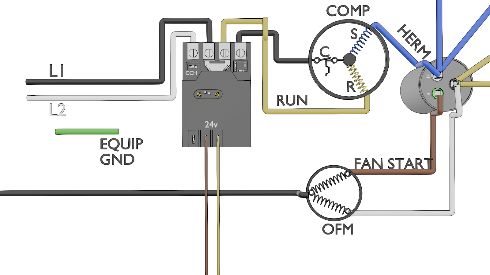
Dedicated CAP terminal to Capacitor C
Connect Fan Wire
In this example, OF1 was the only wire that was disconnected and reconnected.

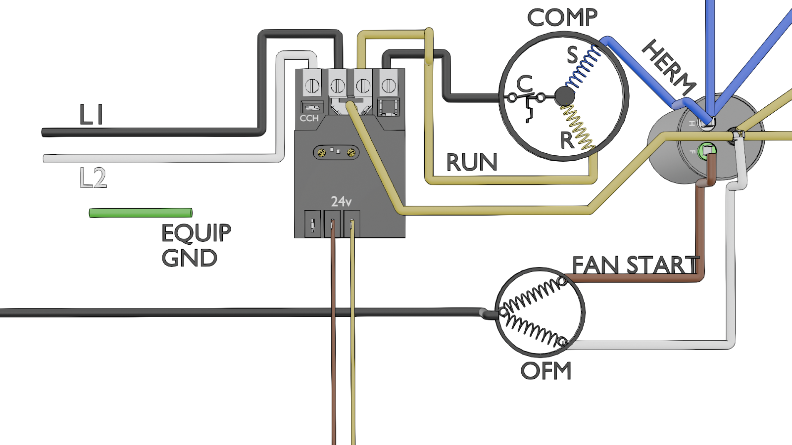
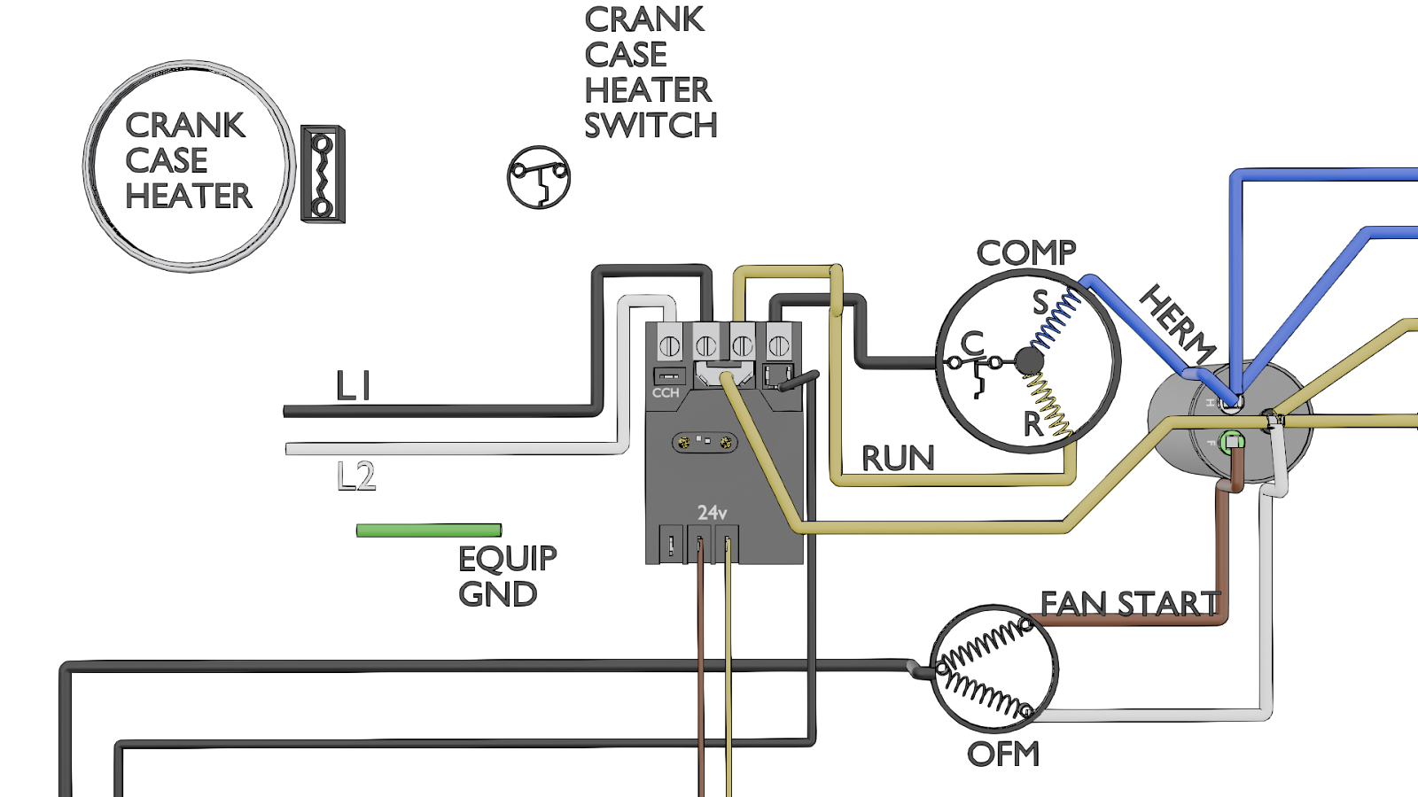
Wiring the Crankcase Heater
A crankcase heater (CCH) is a small resistive heater wrapped around the base of the compressor. Its job is to keep the compressor oil warm during the off-cycle. For it to work, the CCH must have power when the compressor is OFF. The SureSwitch has terminals specifically for this purpose.
Logic: The heater needs a complete circuit. We will provide one leg of power constantly from L1. The SureSwitch will provide the other leg of power only when the compressor is de-energized.
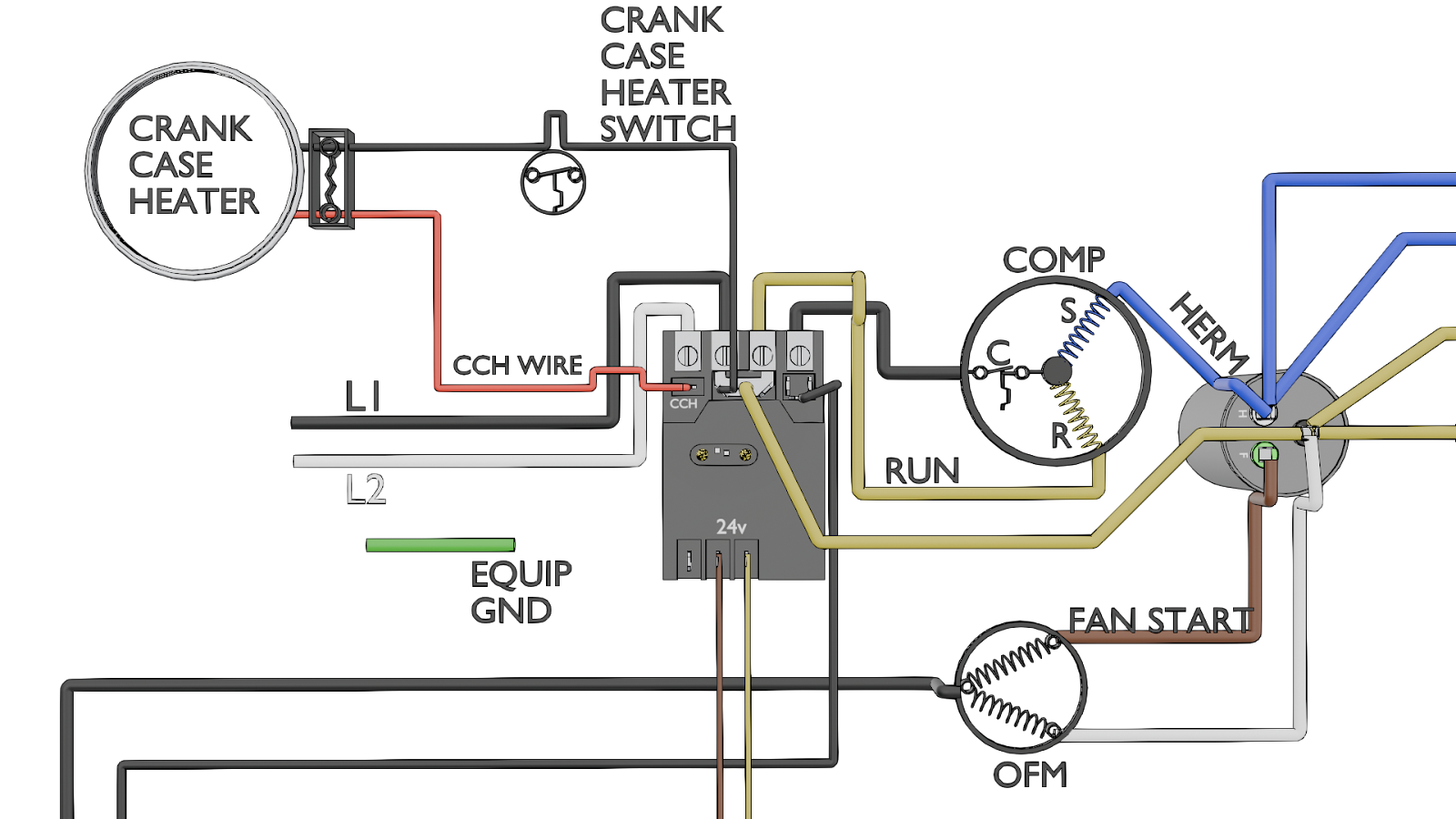
Connection:
- Take one wire from the crankcase heater and connect it to the L1 terminal, alongside the main power wire.
- Take the other wire from the crankcase heater and connect it to the terminal marked T2/CCH.
Connect one of the Crank Case Heater Wires to the CCH Terminal on the L2 side.

Connect the remaining wire on the dedicated CCH Terminal on the L1 side.
By following the pictorial diagram, you've successfully completed the upgrade. You didn't just blindly swap wires; you used the diagram as a map to understand the physical path of each circuit. You identified the control wires, the line voltage, and the load voltage, and correctly routed them to a new component with improved functionality.
Using a wiring diagram effectively elevates you from a parts-changer to a true technician who can confidently diagnose, repair, and improve the systems you work on. Keep practicing, and soon that dreaded diagram will be the first tool you reach for.
—JD Kelly
 Related Tech Tips


Comments
To leave a comment, you need to log in.
Log In